
Permanent magnetic speed regulation is a new type of energy-saving and environmentally friendly transmission device. It features a simple structure, non-contact transmission, low alignment requirements, and adaptability to various complex environments, making it widely applied in industries such as petroleum, chemical engineering, and electric power. This paper introduces the basic principle and typical structures of permanent magnetic transmission.
0. Introduction
The magnetic drive pump technology was first proposed by British scholars Charls and Geoffrey Howard in 1940 to solve the leakage problem during the transportation of hazardous media[1]. Subsequently, HMD Company launched an asynchronous permanent magnetic drive pump for sealed transmission in 1962[2]. For a period thereafter, the development of permanent magnetic transmission technology was constrained by the progress of permanent magnetic materials. It was not until the 1980s that Japan's Sumitomo Special Metals developed a new cobalt-free high-performance neodymium-iron-boron permanent magnetic material, which boosted the advancement of permanent magnetic transmission technology[3]. In 1995, MagnaForce of the United States successfully developed two products for the first time using high-performance permanent magnetic materials: permanent magnetic couplings and permanent magnetic speed regulators, which deliver excellent energy-saving effects in operation[4].In industrial production, variable frequency speed regulators occupy large floor space and have a high repair rate. They contain a large number of electronic components, which complicates maintenance work, leads to long maintenance cycles, delays enterprise production schedules and increases maintenance costs. In contrast, permanent magnetic speed regulators feature a simpler structure and easier troubleshooting, which can significantly reduce enterprises' maintenance costs. As most of their components are mechanical structures, they operate more stably than variable frequency speed regulators and are immune to external electromagnetic interference. Moreover, permanent magnetic speed regulators enable soft start during startup and overload protection during operation, effectively extending the service life of motors.
1. Principle of Permanent Magnetic Speed Regulator
The permanent magnetic speed regulator realizes the transmission of torque and rotational speed through the non-contact connection between the motor and the load. The conductor rotor is connected to the motor side. During rotation, it cuts the magnetic induction lines generated by the permanent magnet, inducing electromotive force in the conductor disk and thereby generating eddy currents, which in turn produce an induced magnetic field around the conductor disk. According to Lenz's law, the induced magnetic field opposes the change in magnetic flux that generates the induced current (eddy current), forming a magnetic field opposite to that of the permanent magnet[5]. When the conductor rotor moves in the magnetic field generated by the permanent magnet, the induced magnetic field interacts with the magnetic field of the permanent magnet, increasing the attractive force between them. At this point, the conductor rotor pulls the permanent magnet via traction force, while the other end of the permanent magnet is connected to the load side, achieving the transmission of torque and rotational speed. The distance between the conductor rotor and the permanent magnet is defined as the "air gap". The air gap adjustment mechanism changes the magnetic field intensity acting on the rotating conductor rotor by adjusting the air gap size. The smaller the air gap, the higher the magnetic induction intensity in the environment where the conductor rotor is located, leading to stronger eddy currents and induced magnetic fields. This enhances the interaction force between the two components and enables the transmission of greater torque and rotational speed.
2. Main Structure of Permanent Magnetic Speed Regulation
2.1 Disc Type Permanent Magnetic Speed Regulator
The air gap adjustment mechanism, conductor rotor and permanent magnet are the main components of the disc-type permanent magnetic speed regulator. The air gap adjustment mechanism mainly regulates the rotational speed and torque by adjusting the size of the "air gap", and its speed regulation principle is illustrated in Figure 2.1.
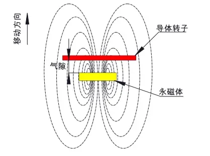
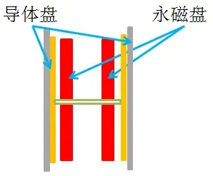
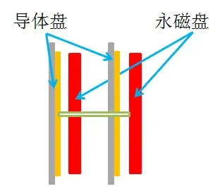
Disc governors can be classified into ABBA type and ABAB type according to the positional relationship between their conductor rotors and permanent magnets. Figure 2.2a and Figure 2.2b illustrate the structural forms of the ABBA type and ABAB type respectively. From their structural characteristics, it can be seen that the ABBA type adopts a symmetrical structure. During operation, the attractive forces exerted by the permanent magnets on the conductor rotor are symmetrical, which can eliminate the axial force between them, reduce vibration, and allow a greater degree of misalignment. In contrast, the ABAB type features an asymmetrical structure, where the axial forces applied by the permanent magnets to the conductor rotor act in the same direction. This intensifies vibration during permanent magnet transmission; moreover, the vibration becomes more severe under poor alignment conditions, resulting in increased damage to the motor.
2.2 Cylindrical Speed Regulator
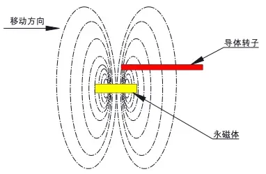
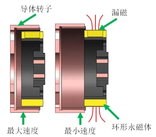
The cylindrical speed governor shares the same structural composition as the disc speed governor, both consisting of a conductive rotor, permanent magnets, and an adjusting mechanism. They differ in shape, as all components of the cylindrical speed governor adopt an annular structure. There are also differences in the speed regulation process: the cylindrical speed governor moves the permanent magnets left and right via the adjusting mechanism to reduce or increase the coupling area with the conductive rotor. As shown in Figure 2.3b, during speed regulation, the size of the meshing surface determines the magnitude of transmitted torque and rotational speed. However, magnetic flux leakage occurs when the meshing surface is relatively small, posing potential safety hazards to the surrounding working environment. In terms of heat dissipation, the cooling fins of the cylindrical type are arranged at the same radial position, failing to form a pressure difference and thus resulting in poor heat dissipation performance. By contrast, the cooling fins of the disc type are distributed along the radial direction, which can create a pressure difference to accelerate air flow and enhance the heat dissipation capacity of the conductive rotor. The cylindrical type has higher requirements for centering during installation, and a higher parallelism tolerance is required axially for the coupling area between the conductive rotor and permanent magnets. In addition, the area of the conductive rotor corresponding to per unit permanent magnet is relatively small. Under the same power condition, compared with the disc permanent magnet speed governor, the cylindrical type requires more magnetic blocks, which increases manufacturing costs[6].
2.3 Shielded Sleeve Permanent Magnet Governor
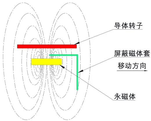
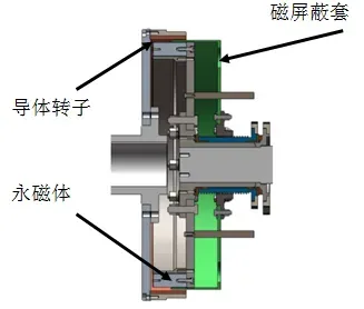
The structural forms of the shielded sleeve permanent magnet governor and the cylindrical permanent magnet governor are relatively similar. As shown in Figure 2.4a, the shielded sleeve permanent magnet governor consists of a conductor rotor, permanent magnets and a magnetic shielding sleeve. Speed regulation is realized by changing the position of the magnetic shielding sleeve to increase or decrease the coupling area between the conductor rotor and the permanent magnets. The existing problems of the cylindrical permanent magnet governor also occur in the shielded sleeve permanent magnet governor. Meanwhile, the adoption of the magnetic shielding sleeve raises the manufacturing cost of the governor. In addition, a certain radial gap reserved between the conductor rotor and permanent magnets for the movement of the magnetic shielding sleeve increases the distance between the conductor rotor and the permanent magnet disc, thus reducing the transmission efficiency.
3. Conclusion
By comparing two different structures of disc permanent magnet speed regulators (ABBA type and ABAB type), cylindrical permanent magnet speed regulators and shielding sleeve type permanent magnet speed regulators, the disc permanent magnet speed regulator (ABBA type) boasts the advantages of simple structure, excellent heat dissipation capacity, convenient installation and maintenance, and large allowable alignment error. In the production process of enterprises, the disc permanent magnet speed regulator (ABB type) can deliver higher energy-saving and environmental protection performance, which helps improve the production capacity of enterprises.
References: [1] Yuan Danqing, He Youquan, Chen Xiangyang, et al. Research Status and Development Prospect of Magnetic Pumps[J]. Magnetic Materials and Devices, 2011, 042(002): 1-3,8. [2] Wang Hongqun, Huang Zhijian, Xie Minghui, et al. Overview and Development Prospect of Permanent Magnet Transmission Technology[J]. Chinese Journal of Construction Machinery, 2016(6). [3] Zhu Jinghan. Rare Earth Permanent Magnet Materials and Their Applications[J]. Electrotechnical Journal, 1988(01): 13-17. [4] Liu Ting'an. A New Type of Permanent Magnet Transmission Technology[J]. Mining Equipment, 2014(01): 59-62. [5] Liu Yan. Extended Application of Lenz's Law[J]. Technology Innovation and Application, 2014(13): 273-274. [6] Jing Changcai. Comparative Analysis of New Cylindrical and Disc Permanent Magnet Speed Regulators[J]. Shenhua Science and Technology, 2018, 16(05): 88-90.